Page 2 of 4
Re: A10 auto level sensor
Posted: Tue Sep 18, 2018 7:20 pm
by Gingko
Sorry, the red line seems to connect to VCC, let me confirm tomorrow!

Re: A10 auto level sensor
Posted: Wed Sep 19, 2018 6:31 pm
by Gingko
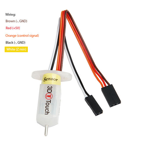
brown--GND
red--VCC
need to do a little modification for the connector of 3 pins.
Re: A10 auto level sensor
Posted: Wed Sep 19, 2018 7:04 pm
by Wolle82
need to do a little modification for the connector of 3 pins.
Please... can U show us a complete working setup? No mistakes, please. I am confused now.
This image is from
http://www.geeetech.com/wiki/index.php/ ... ing_Sensor:
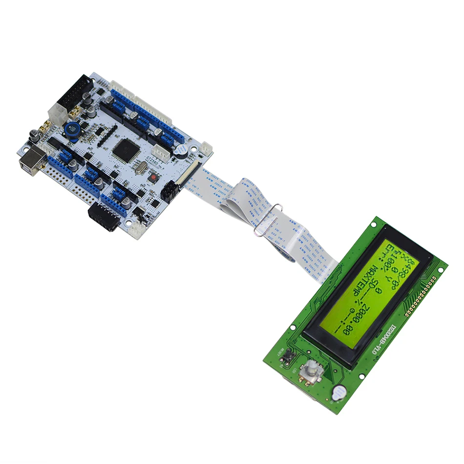
This is the board:
So... can U please show
EXACTLY how to connect? Don't change colours.
Re: A10 auto level sensor
Posted: Fri Sep 21, 2018 4:47 am
by gdachs
You have to exchange red and orange.
Re: A10 auto level sensor
Posted: Fri Sep 21, 2018 6:26 pm
by Wolle82
So it looks like:
Code: Select all
Endstop connector:

VCC [red]       |   VCC
Z_MAX [orange]  |   Z_MIN [white]
GND [brown]     |   GND [black]
VCC             |   VCC
Y_MAX           |   Y_MIN
GND             |   GND
VCC             |   VCC
X_MAX           |   X_MIN
GND             |   GND
Re: A10 auto level sensor
Posted: Fri Sep 21, 2018 6:54 pm
by Wolle82
Here is a picture of correct wireing:
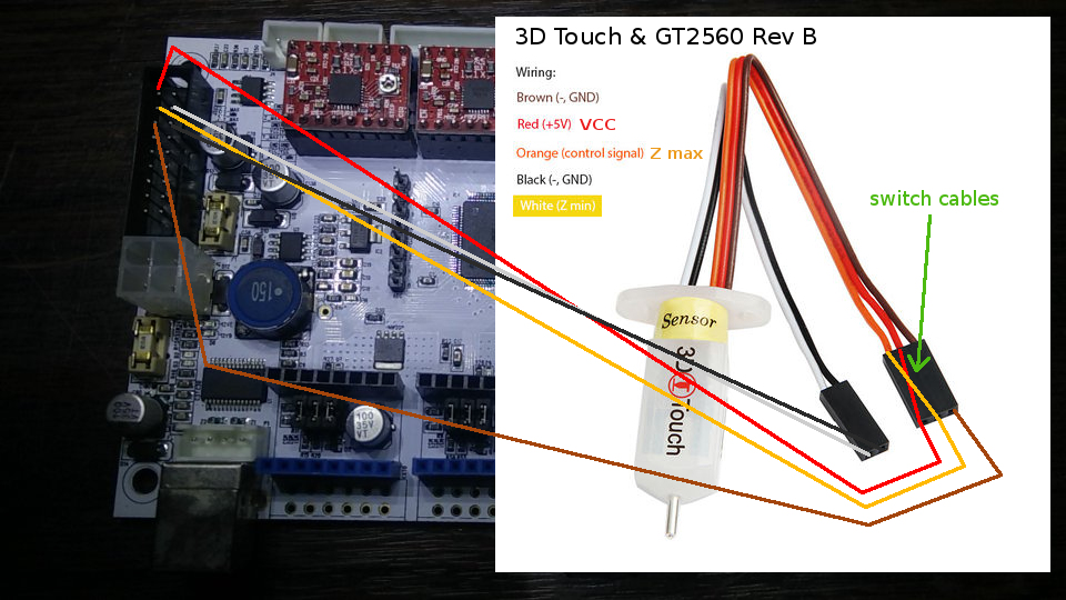
- 3d_touch_a10.jpg (302.08 KiB) Viewed 29763 times
Have fun!
Re: A10 auto level sensor
Posted: Fri Sep 21, 2018 7:18 pm
by Wolle82
Well now, when there is someone out there who can give us a cool or simple STL file for a 3DTouch mount for the Geeetech A10 it would be very nice! Maybe you have designed one yourself... Please share.
Re: A10 auto level sensor
Posted: Wed Sep 26, 2018 3:31 pm
by Wolle82
Re: A10 auto level sensor
Posted: Sat Oct 06, 2018 4:50 am
by RepMike
Question - can anyone point me to a tutorial on how to setup a Capacitive Proximity Sensor with the Geetech A10? Can I use the connectors on the Extruder? If so, how are they being wired?
Thank you in advance
Re: A10 auto level sensor
Posted: Wed Oct 10, 2018 4:18 pm
by Wolle82
The A10 has no extra connectors to connect the sensor at the hotend/extruder... you connect it to the Z endstop on the mainboard directly as I know.
Further there a 3 methods to connect it to the Z endstop:
1. directly connect the sensor (not recommended - voltage to low with 5V for the sensor. The sensor is about 6-36V.)
2. use an octocoupler (safest but more tricky - use 24V with the sensor, separated 5V from the mainboard for the signal)
3. use a voltage devider (easy and cheap - use 24V with the sensor and devide the voltage to 5V for the signal)
Hint:
When U want to use the voltage devider (3.) you should know that the sensor (
LJC18A3-H-Z/BX) itself has a build-in resistor at
10kOhm. Use a
2.2kOhm resistor to devide the
voltage from 24V to 4.5V. When U got an other sensor find out its resistor value first (if present). That should be the easiest way... And don't forget to solder the resistor first before you connect to the board!
Here is my mount:
https://www.thingiverse.com/thing:3146974