Page 1 of 1
GT2560 board schematics
Posted: Fri Feb 05, 2016 3:24 am
by myattorneyusa
Can some one post GT2560 board schematics?
If not, at least, tell me what is Q5 on the board? What is nominal or substitute of Q5? Why do i need to know? Because, mine burnout. This is what happen. I was printing big thing, 5 hours print on my G2S. Hotend cooling fan went out first. Replacing cooling fan didn't help, new fan didn't work. After visual examining of GT2560 board I discover that Q5 looks different. Everything is working except hotend cooling fan.
Thx
Re: GT2560 board schematics
Posted: Fri Feb 05, 2016 11:46 am
by Mark
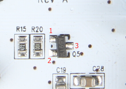
the Q5 is the one here:
name specific type
mosfet SOT-23 AP2306AGN
And you can remove the Q5, short the pin2(GND) and pin3(PWM FAN) using the soldering iron, then you'll make it work too:
- PWM 风扇电路01.jpg (132.77 KiB) Viewed 25182 times
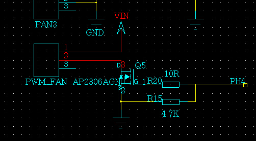
- PWM 风扇电路.jpg (99.47 KiB) Viewed 25182 times
Re: GT2560 board schematics
Posted: Sat Feb 06, 2016 2:33 am
by myattorneyusa
Thank you Mark for reply. The schematics diagram:
http://www.geeetech.com/forum/download/file.php?id=532
Replacement for Q5 transistor could be located at:
http://alltransistors.com/mosfet/crsear ... 0.09&caps=
I find that 70L02H
http://www.datasheetbay.com/datasheets/ ... 0L02H.html transistor is a good, "direct" replacement. You can salvage one from old PC mobo. Yes, It's bigger, but has more power, 66A at 25v. You have to mount it vertically
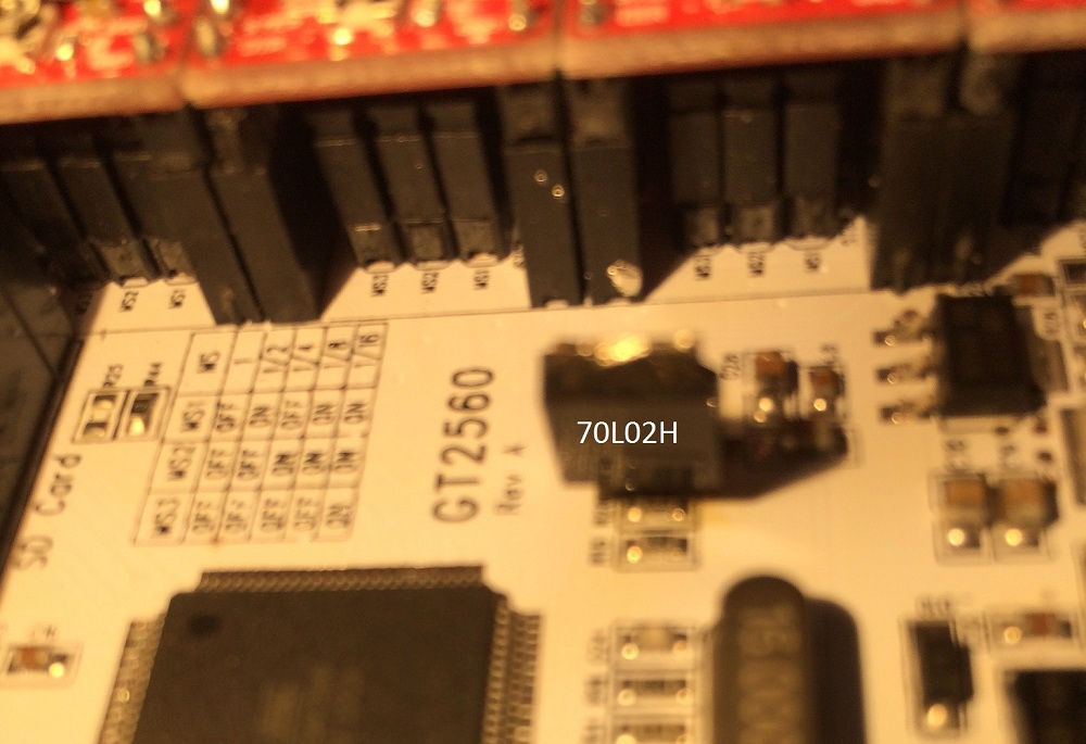
- Q5 replacement, Mount of 70L02H transistor on GT2560 board
- GT2560.JPG (170.1 KiB) Viewed 25141 times
No radiator needed, don't have to change any of resistors on GT2560 board. It Will give you full range of PWM from 0v to 12v or 0v to 24v (if you use 24v power supply) at 66A. After involuntary upgrade, I can use it (fan control software) to control burning Laser or any device which require high power output.
Re: GT2560 board schematics
Posted: Tue Feb 09, 2016 10:28 pm
by Mark
haha nice work!

Re: GT2560 board schematics
Posted: Fri Jan 27, 2017 10:47 pm
by elfag.blogg.no
myattorneyusa wrote:Thank you Mark for reply. The schematics diagram:
download/file.php?id=532
Replacement for Q5 transistor could be located at:
http://alltransistors.com/mosfet/crsear ... 0.09&caps=
I find that 70L02H
http://www.datasheetbay.com/datasheets/ ... 0L02H.html transistor is a good, "direct" replacement. You can salvage one from old PC mobo. Yes, It's bigger, but has more power, 66A at 25v. You have to mount it vertically
GT2560.JPG
No radiator needed, don't have to change any of resistors on GT2560 board. It Will give you full range of PWM from 0v to 12v or 0v to 24v (if you use 24v power supply) at 66A. After involuntary upgrade, I can use it (fan control software) to control burning Laser or any device which require high power output.
Hi. Mine is also burn out. Do you think i can use IRF840 mosfet? Or this one IRF9530N
Re: GT2560 board schematics
Posted: Tue Feb 21, 2017 2:52 am
by myattorneyusa
Yes, you can. Also, you can use any MOSFET Driver which compatible with Arduino, like IRF520 MOSFET Driver Module and so on.
Re: GT2560 board schematics
Posted: Tue Feb 21, 2017 1:43 pm
by elfag.blogg.no
myattorneyusa wrote:Yes, you can. Also, you can use any MOSFET Driver which compatible with Arduino, like IRF520 MOSFET Driver Module and so on.
Thank you for your help
